
http://dx.doi.org/10.15649/2346030X.975
Exhaust gases reuse in natural gas compression stations for electricity generation.
Carlos Javier Noriega-Sanchez1
Gustavo Guerrero-Gómez22
Fernando Freitas-Czubinski3
- Universidad Francisco de Paula Santander, Ocaña - Colombia. E-mail: cjnoriegas@ufpso.edu.co Autor de correspondencia
- Universidad Francisco de Paula Santander, Ocaña - Colombia.
- Universidad Federal de Santa Catarina, Florianópolis - Brasil.
Recibido: 19 de noviembre de 2020.
Aceptado: 19 de diciembre de 2020.
Publicado: 1 de enero de 2021.
Atribución 4.0 Internacional (CC BY 4.0)
Abstract— In view of worldwide concern for the increase in energy consumption, as well as the application of viable alternatives that allow a better use of available energy sources, thermal waste has emerged as an energy alternative in industrial applications in which it is generated. In this sense, the present work analyses the energy potential of combustion gases emitted by a compression station, which can be used as heat source for a Rankine power cycle, which operates with different working fluids, including nine of organic type and the carbon dioxide (CO2). The simulations demonstrated the capacity of the working fluids to increase the energy efficiency of the installation from the exhaust gases of the compression station, where toluene and CO2 stand out for presenting the highest efficiency levels, 21 and 20%, respectively. With the target of generating power, the results showed that refrigerant fluids considered in this analysis are not suitable at the temperature levels evaluated.
Keywords: power cycle, numeric simulation, organic fluid, energy balance.
The choice of working fluid for organic Rankine cycle (ORC) is a complex task due to thermophysical properties, working conditions, diverse range of heat sources and the quantity of fluids considered in the analyses [1- 5]. Therefore, there is not a single fluid that has been identified as ideal for this class of systems [6]. In general, the studies consulted show that linear hydrocarbons (HC), ramified and aromatic refrigerants, as well as organic refrigerants have desirable thermodynamic properties for use in Rankine power cycles, however, they present a certain risk of flammability and environmental disadvantages [7].
Probably one of the most prominent criteria for selecting working fluids for ORC are those of the environmental type [1, 7]. The potential use of non-polluting fluids with low ozone depletion potential (ODP) and global warming potential (GWP), for power generation and vapor compression refrigeration cycles, has become one of the main driving forces of this research line [3, 8]. This is mainly associated with restrictions on the use of fluids, which are certainly harmful to the environment [9]. Due to these characteristics, natural refrigerant fluids such as carbon dioxide (CO2) have been identified recently as strong candidates to be used in power cycles, meeting the requirements of the new generation of working fluids [10]. The idea of using this fluid in thermodynamic cycles is not new, being the first records in 1866, with its consolidation in 1886, when CO2 started to be widely used in refrigeration and air conditioning systems [11]. However, the emergence of CFCs in the 1930s caused the replacement of CO2 in most of these systems. In the 1990s, the environmental impacts associated with the use of CFCs were analyzed and the search for environmentally safe working fluids was started, returning to the interest for these fluids.
Despite the attractive use of natural fluids such as CO2, other competing fluids, mainly hydrocarbon-based refrigerants (HFCs), which obviously exhibit much higher ODP and GWP, often exhibit higher levels of thermodynamic performance in power cycles, especially with low temperature heat sources, such as internal combustion engines [1, 4, 12]. More specifically, the results reported by [1] show that, although the selection of the most appropriate working fluid depends on several considerations (heat sources temperature, working fluid properties, safety issues, etc), refrigerants like R123, R134a, R152a, R245fa and R32 appear in terms of total exegetic efficiency, a good choice to convert low-grade heat into energy, despite its high GWP.
In view of applications that allow a better use of available energy sources, the goal of this article is analyze the energy potential of combustion gases emitted by a compression station, which can be used as power cycle heat source. This power cycle operates with several organic working fluids (5 HFCs and 4 HCs) and CO2 as a natural type reference fluid, in order to increase the energy efficiency of the installation, as well as reduce greenhouse gas emissions from the natural gas burning in these facilities.
Even though low-temperature waste heat has a reduced energy potential and less economic value than high-temperature waste, this heat source is very numerous. In fact, about 60% of the residual heat exhibits temperatures below 230 °C, and about 90% below 316 °C, as reported by [13]. However, due to the lack of efficient recovery methods, low-grade waste heat has generally been discarded by the industry and has become an environmental problem due to thermal pollution. Therefore, strategies focused on the use or conversion of this heat into electricity or cold are attracting much interest. This not only improves the energy efficiency of industrial processes, but also reduces thermal pollution caused by the direct release of this heat into the environment.
Systems that use waste heat to generate electricity often use this heat to generate steam and then drive a turbine. However, the steam power cycle becomes less profitable at low temperature (<340 °C), since low pressure steam requires larger equipment [14]. In addition, the absence of sufficient energy to overheat the steam ends up producing the steam condensation in the turbine, which poses a risk of blades erosion [14 - 16]. In contrast, in order to take advantage of the energy available at these levels, the organic Rankine cycle (ORC) was proposed.
ORC technology has been widespread since the mid-1970s. The ORC's peculiarity about the traditional steam Rankine cycle is based on the working fluid. In ORC, an organic fluid is used instead of water. This component is typically a refrigerant, hydrocarbon or silicone oil, among others. Compared to water, these fluids stand out for having a low boiling temperature and they have the potential to recover heat at temperature levels below those found in Rankine steam cycles. This characteristic makes it the most suitable power cycle to recover heat from low (<230 °C) and medium temperature (<370 °C) thermal sources, usually found in the solar, geothermal, biomass and industrial waste areas, among others [17, 18].
a. Heat source
In the hydrocarbon sector, combustion gases are among the most common thermal waste. These gases, when emitted at constant flows and adequate quantities, can be recovered and used in several applications, such as the production of electricity or cold. Natural gas is one of the products of this sector, however, due to the distance between the extraction and destination points, it must be compressed along the pipeline through compression stations [19].
Compression stations are auxiliary facilities for natural gas transportation distributed by gas pipelines. The fluid must be constantly pressurized to maintain the required pressure levels for being distributed and used. Although necessary, these stations have the disadvantage of requiring energy to power the gas compression equipment. As such facilities may be located in regions not served by the electrical distribution network, currently the energy used comes from the combustion of a part of the natural gas that is transported. The combustion gases from these compressor units are released into the environment with possibly sufficient temperature and mass flow levels to be reused.
Therefore, in the present work, the combustion gases produced by a VHP Series L7044GSI engine from a gas pipeline compression station were considered [20], whose operating conditions at 1200 rpm necessary for the development of the simulations of this work are presented in Table 1.
Table 1: Characteristics of heat source in this work (hs subscript is heat source).
Parameter |
Symbol |
Value |
Heat source pressure |
Phs,in |
100 kPa |
Combustion gas temperature |
Ths,in |
637 °C |
Mass flow |
ṁhs |
1.42 kg s-1 |
Source: Own elaboration.
b. Power cycle working fluids
A bibliographic review about organic working fluids suitable for power cycles and temperature levels found in the exhaust gases of the compression station under analysis provided the working fluids listed in Table 2 [21, 22]. Although CO2 is not an organic fluid but a natural refrigerant, this was included in the simulation in order to evaluate its potential for power production against more suitable organic fluids for this application. Regardless of the fluid being organic or natural, none of these affects the ozone layer.
Table 2: Working fluids selected for analysis.
Fluid |
Fluid type |
ODP |
GWP |
n-Butane |
HC |
0 |
4 |
n-Pentane |
HC |
0 |
4 |
n-Hexane |
HC |
0 |
3 |
Toluene |
HC |
0 |
2.7 |
R32 |
HFC |
0 |
650 |
R41 |
HFC |
0 |
97 |
R125 |
HFC |
0 |
2800 |
R143a |
HFC |
0 |
3800 |
R161 |
HFC |
0 |
12 |
CO2 |
Natural |
0 |
1 |
Source: Own elaboration based on contributions from [21, 22].
c. Power cycle models
The basic configurations of Rankine cycle used to organic fluids and Brayton cycle for CO2 are presented in Figure 1. The organic Rankine cycle to be analyzed consists of four fundamental processes: (1-2) compression of the organic working fluid in liquid state at high pressure level by means of a pump; (2-3) direct heating through a heat exchanger using combustion gases; (3-4) expansion to the initial pressure level, called low pressure, through a turbine to generate mechanical work; and (4-1) cooling to the initial temperature level, returning to the conditions of step (1). In the case of CO2, the cycle to be analyzed will be a Brayton type. This cycle consists of the same four processes, with the exception that the CO2 remains in a supercritical state, that is, at pressure and temperature greater than its critical conditions (Pcrit = 7.4 MPa and Tcrit = 31 ° C), during all cycle steps. The pressure increase during the process (1-2) is carried out through a compressor – Even though the Brayton cycle can reach higher temperatures and therefore reach better efficiency rates, its compression work requires a greater amount of energy, thus reducing the net work produced by the system.
The most significant considerations for developing the simulations are presented below:
• It was considered that the exhaust gases left the evaporator or gas heater (Point 6 in Figure 1) at 120 °C to avoid condensation problems of water vapor in the gases and risk of H2SO4 formation.
• Pressure drops within cycle components are not considered.
• The isentropic efficiency of the turbine and pump (or compressor in the Brayton cycle) was considered to be 80% [21].
• The condensing temperature was fixed at 40 °C (Point 1 in Figure 1) - Note that for this cooling temperature, CO2 can only be considered as working fluid if the cycle operated is Brayton.
• Variations in kinetic and potential energy were excluded and all components of the cycle were considered adiabatic.
• All the heat emitted by the exhaust gases was completely absorbed by the working fluid and the minimum quality value at the turbine outlet by working fluid was adopted as 1 (x =1).
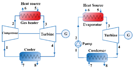
Figure 1: Configurations of (a) basic Rankine cycle and (b) Brayton cycle simulated
Source: Own elaboration.
• The minimum pressure of the working fluid within the cycle (Points 1 and 4 in Figure 1) was defined as the saturation pressure for a temperature of 40 °C. For the CO2, as the Brayton cycle was adopted, a minimum pressure of 8 MPa was established – Note that this pressure is higher than its critical pressure.
• A numerical calculation routine was developed using Matlab® software and the CoolProp library of thermophysical properties [23], using the thermodynamic equations of energy and mass balance widely known and used in the power cycle literature [2, 3, 21]. On the other hand, the equation from which the cycle efficiency was determined as a function of each working fluid is presented in Eq. (1), where represents the net power of the cycle (Turbine power minus the power of the pump/compressor) and the heat transfer rate received by the working fluid between points 2 and 3 of Figure 1.
![]() (1)
(1)
• A different turbine inlet temperature was adopted for each working fluid, respecting the safety limits (in terms of flammability, explosion risk and thermal degradation) and correlation equation of CoolProp® library. The values adopted for each fluid are presented in Table 3. For CO2, a difference of 20ºC was adopted in relation to the heat source temperature to determine the turbine inlet temperature since this fluid has a thermal degradation temperature greater than 1000 °C [21]. For the other fluids was used 10 ºC lower than its maximum temperature, in order to reduce the risks of thermal degradation.
• The validation of the computational numerical script developed in Matlab® was validated with other works published in the literature and can be consulted in the following references already published by the authors [2, 3, 24].
Table 3: Turbine inlet temperatura for each working fluid.
Fluid |
Temperature [°C] |
n-butane |
217 |
n-pentane |
171.85 |
n-hexane |
167 |
Toluene |
308.6 |
R32 |
224.67 |
R41 |
152 |
R125 |
220 |
R143a |
141.85 |
R161 |
217 |
CO2 |
Ths-20 |
Source: Own elaboration.
The calculation routine developed includes the optimization of the turbine inlet pressure in order to maximize the net power production. In that way, the maximum power produced for each considered fluids is shown in Figure 2. It can be seen that for the basic configuration, the toluene obtained the highest net power, around 0.17 MW, that is, the system can produce 170 kW from the combustion gases that are currently discharged into the environment. CO2 is after toluene, the working fluid that produces the highest power in the cycle (0.16 MW). In general, the other refrigerant fluids present a low use of combustion gases except for R32, this is due to the fact that the maximum temperature at which these can operate in the system without risk of thermal degradation is considerably lower when compared to toluene and CO2 temperatures.
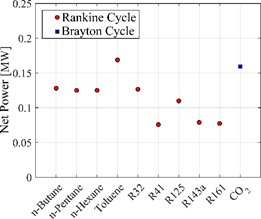
Figure 2: Net power produced according to the working fluid and power cycle.
Source: Own elaboration.
Figure 3 shows the optimum pressure value required for each working fluid. For the fluids operating in the Rankine cycle, it is observed that the HC fluids presented values between 1 MPa and 8 MPa, approximately, as expected. Refrigerant fluids present a much higher pressure than HC fluids, with a range between 8 MPa and 36 MPa, except to R161 whose pressure value was the lowest of HFCs, 4 MPa. CO2 is the fluid with the highest maximum operating pressure in the system ~ 83 MPa, this due to supercritical state in which this fluid operates according to Brayton cycle.
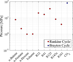
Figure 3: Optimal pressure for each working fluid.
Source: Own elaboration.
The pressure values presented in Figure 3 respect the correlation limits for the properties calculation, and it should be taken only as illustrative values since the feasibility analyses in terms of commercial availability and safety requirements are outside the scope of this work.
Figure 4 shows the mass flow value required to reach the maximum net power (see Figure 2). In this scenario, once again toluene is highlighted for requiring the lowest mass flow of all fluids (~ 1.2 kg s-1). In general, the HC fluids showed a decrease in the mass flow with the increase of carbon number, on the other hand, the HFC fluids are the ones that demand the highest mass flow in the system to reach the maximum net power of the cycle.
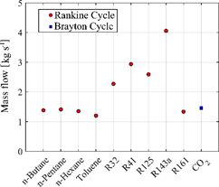
Figure 4: Mass flow required be each working in simulated configurations.
Source: Own elaboration.
Finally, another pertinent analysis comes from the data presented in Figure 5 regarding the low pressure (or condensation pressure) of each fluid, the analyzes are generally made in comparison to atmospheric pressure (horizontal blue line in Figure 5). Values such as those presented by HCs fluids, lower than the atmospheric pressure, indicate the possibility of problems with infiltration of atmospheric air in the condenser (between points 4 and 1 in the Figure 1a). The apparent high value of the low CO2 pressure is due to its high critical pressure compared to the saturation pressure of the other selected fluids. It is noteworthy that both n-butane and n-pentane (both HCs) had condensation pressures values higher than that of the atmosphere.
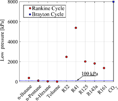
Figure 5: Low pressure in kPa for each working determined by temperatura saturation wich a minimiu temperatura of 40°C (excep to CO2 fixed at 8000 kPa).
Source: own elaboration.
In general, toluene was presented as a very interesting fluid since it has the highest power produced and the lowest mass flow compared to the other fluids analyzed. On the other hand, the cycle that operate with HC fluid needs less complex components, smaller and possibly lower costs. CO2 appears as an alternative in relation to the net power value, but the components of its cycle still need a lot of development in order to be used [22].
This study was limited to thermodynamic variables, being necessary economic and technical studies of the cycle components. Also, other parameters of the cycle, such as the size of the heat exchangers, can be optimized in future works.
The simulations demonstrated the energy recovery potential from exhaust gases of a compression station. In this way, the points of great relevance of the study are discussed below:
• In order to generate power, it is concluded that refrigerant fluids considered in this study are not suitable working fluids for the temperature levels studied. Furthermore, the high cost of such fluids, taking into account mass flows for production under maximum power conditions, is unfavorable.
• Regarding the thermal efficiency of the system, toluene and CO2 present values of 21 and 20%, respectively, and therefore, they are the working fluids that make the best use of the energy available in the combustion gases of the compression station.
Finally, a brief analysis in the natural gas quantity that would not be withdrawn for new combustion (it would be saved) can be presented in order to supply the same exhaust gases thermal power. Considering the LHV (lower heating value) of natural gas of 50 MJ kg-1 [25], it could be saved ~56.3 kg h-1 of natural gas with the utilization of a power cycle at the facility.
Although the coupling between exhaust gases and the high temperature heat exchanger (or steam generator) in the simulation was done directly, it should be noted that in practice there is a tendency to use an intermediate fluid such as thermal oil that transfer the heat from the exhaust gases to the working fluid, if it is flammable (HC or HFC fluids for example). Despite it increases the installation cost, the use of an intermediate fluid reduces the potential risk by the use of flammable fluids, as well as promoting a better use of the heat source ensuring a better temperature distribution in the cascade heat exchanger (smaller temperature gradients generate less irreversibilities).
Lastly to reduce the likelihood of risks related to the flammability of working fluids, especially hydrocarbons, it must be ensured that the system always operates at pressures above atmospheric in order to avoid infiltration of atmospheric air into the working fluid, this condition could imply the use of saturation temperature above 40 ° C in the condenser for this class of fluids.
[1] A. Mahmoudi, M. Fazli, and M. R. Morad, ‘A recent review of waste heat recovery by Organic Rankine Cycle’, Applied Thermal Engineering, vol. 143, pp. 660–675, Oct. 2018.
[2] C. J. N. Sanchez, N. A. García, and G. G. Gómez, ‘Carbon dioxide mixtures for organic power cycles using waste heat sources’, J. Phys.: Conf. Ser., vol. 1409, p. 012016, Nov. 2019.
[3] C. J. Noriega Sanchez, L. Gosselin, and A. K. da Silva, ‘Designed binary mixtures for subcritical organic Rankine cycles based on multiobjective optimization’, Energy Conversion and Management, vol. 156, pp. 585–596, Jan. 2018.
[4] H. Chen, D. Y. Goswami, and E. K. Stefanakos, ‘A review of thermodynamic cycles and working fluids for the conversion of low-grade heat’, Renewable and Sustainable Energy Reviews, vol. 14, no. 9, pp. 3059–3067, Dec. 2010.
[5] N. Chagnon-Lessard, F. Mathieu-Potvin, and L. Gosselin, ‘Geothermal power plants with maximized specific power output: Optimal working fluid and operating conditions of subcritical and transcritical Organic Rankine Cycles’, Geothermics, vol. 64, pp. 111–124, Nov. 2016.
[6] D. Wang, X. Ling, H. Peng, L. Liu, and L. Tao, ‘Efficiency and optimal performance evaluation of organic Rankine cycle for low grade waste heat power generation’, Energy, vol. 50, pp. 343–352, Feb. 2013.
[7] B. F. Tchanche, G. Papadakis, G. Lambrinos, and A. Frangoudakis, ‘Fluid selection for a low-temperature solar organic Rankine cycle’, Applied Thermal Engineering, vol. 29, no. 11, pp. 2468–2476, Aug. 2009.
[8] B. Dai, M. Li, and Y. Ma, ‘Thermodynamic analysis of carbon dioxide blends with low GWP (global warming potential) working fluids-based transcritical Rankine cycles for low-grade heat energy recovery’, Energy, vol. 64, pp. 942–952, Jan. 2014.
[9] I. Sarbu, ‘A review on substitution strategy of non-ecological refrigerants from vapour compression-based refrigeration, air-conditioning and heat pump systems’, International Journal of Refrigeration, vol. 46, pp. 123–141, Oct. 2014.
[10] J. M. Calm, ‘The next generation of refrigerants – Historical review, considerations, and outlook’, International Journal of Refrigeration, vol. 31, no. 7, pp. 1123–1133, Nov. 2008.
[11] M.-H. Kim, J. Pettersen, and C. W. Bullard, ‘Fundamental process and system design issues in CO2 vapor compression systems’, Progress in Energy and Combustion Science, vol. 30, no. 2, pp. 119–174, Jan. 2004.
[12] T.-C. Hung, ‘Waste heat recovery of organic Rankine cycle using dry fluids’, Energy Conversion and Management, vol. 42, no. 5, pp. 539–553, Mar. 2001.
[13] DOE, ‘Waste Heat Recovery: Technology and Opportunities in U.S. Industry’, BCS, 2008.
[14] B. F. Tchanche, Gr. Lambrinos, A. Frangoudakis, and G. Papadakis, ‘Low-grade heat conversion into power using organic Rankine cycles – A review of various applications’, Renewable and Sustainable Energy Reviews, vol. 15, no. 8, pp. 3963–3979, Oct. 2011.
[15] A. I. Papadopoulos, M. Stijepovic, and P. Linke, ‘On the systematic design and selection of optimal working fluids for Organic Rankine Cycles’, Applied Thermal Engineering, vol. 30, no. 6, pp. 760–769, May 2010.
[16] E. Wali, ‘Optimum working fluids for solar powered Rankine cycle cooling of buildings’, Solar Energy, vol. 25, no. 3, pp. 235–241, Jan. 1980.
[17] S. Quoilin, M. V. D. Broek, S. Declaye, P. Dewallef, and V. Lemort, ‘Techno-economic survey of Organic Rankine Cycle (ORC) systems’, Renewable and Sustainable Energy Reviews, vol. 22, pp. 168–186, Jun. 2013.
[18] R. El Chammas, D. Clodic, and P. Dewallef, ‘Combined Cycle for Hybrid Vehicles’, SAE, p. 12, 2005.
[19] M. Hendryx and J. Luo, ‘Natural gas pipeline compressor stations: VOC emissions and mortality rates’, The Extractive Industries and Society, vol. 7, no. 3, pp. 864–869, Jul. 2020.
[20] F. Guerrero Suárez and F. Llano Camacho, ‘Gas natural en Colombia - Gas E.S.P’, Estudios Gerenciales, vol. 19, no. 87, pp. 115–146, Jun. 2003.
[21] E. Macchi and M. Astolfi, Organic Rankine Cycle (ORC) Power Systems. Elsevier, 2017.
[22] Y. Liu, Y. Wang, and D. Huang, ‘Supercritical CO2 Brayton cycle: A state-of-the-art review’, Energy, vol. 189, p. 115900, Dec. 2019.
[23] ‘Welcome to CoolProp — CoolProp 6.4.1 documentation’. http://www.coolprop.org/index.html.
[24] C. J. N. Sánchez and A. K. da Silva, ‘Technical and environmental analysis of transcritical Rankine cycles operating with numerous CO2 mixtures’, Energy, vol. 142, pp. 180–190, Jan. 2018.
[25] Y. Cengel and M. Boles, Thermodynamics: An Engineering Approach, 8th ed. McGraw-Hill Education, 2014.